
Oct 14, 2026
Events
The glossary explains some technical terms and trade names used in this catalog. These terms are explained in a way consistent with vacuum valve technology.
A controller adapting itself to changes in pressure, gas flow, and pumping speed without any manual adjustments. This allows for a completely automatic operation of the system.
The static seals and the seat seal are made of metal. Because these valves are free of lubricants and do not contain any elastomers or plastomers, their outgassing rate is very small and they can be baked at higher temperatures. They are therefore used for extreme UHV applications. With a special actuator they are radiation resistant to higher levels (108 Gy) than elastomer sealed valves.
Short form for "not ferromagnetic".
The relative magnetic permeability μr is measured with a permeameter.
Most VAT valves can optionally be supplied in an antimagnetic version. We distinguish between two classes of antimagnetic valves:
Class 1:
Class 2:
Special materials are used to reach these low values. For stainless steel the manufacturing process is carefully supervised. Small parts with little mass may have μr values above 2.
ASA flanges were originally developed for high pressure applications. Later on, they have been used in vacuum technology. ASA flanges have a larger distance between the mounting holes and the nominal diameter (DN) than other vacuum flanges.
ASA-LP (ASA large port) flanges are ASA flanges with an increased nominal diameter. The outer diameter (O.D.) and the mounting holes are identical to those of the ASA flange. ASA-LP flanges are available for the nominal diameters 2½" to 12".
Example:
Bellows are used to seal the actuating shaft. Only formed and welded metal bellows are used in VAT valves. This sealing technology offers the following advantages:
Small leak rate during actuation
Free of lubricants
Bakeable
The closing direction is defined as the direction in which the gate approaches the seat during closing.
Time between the switching of solenoid voltage and the arriving of the gate in the fully closed, vacuum tight resp. open position.
The data in the catalog shows typical values. They are dependent on the compressed air pressure, the mounting position of the valve, the cross sections and lengths of the compressed air lines as well as on the measuring method and measuring system.
For fast closing systems the expression "total closing time" is used. This is the time between the triggering of the sensor (without sensor response time) and the arrival of the plate in the fully closed position.
The specified compressed air pressures are always overpressures in bar.
Lasting deformation of an elastomer seal after relief. The compression set is depending on the kind of material and has to be considered when defining dynamic seals.
CS = 100 · (ho – h2)/(ho – h1)
CS … Compression set (%)
ho … Original height of seal
h1 … Height of seal in compressed condition
h2 … Height of seal in relieved condition
DeviceNet: DeviceNet® is a digital network serving as a communication network between industrial controllers and I/O devices. It is based on the CAN standard (controller area network). Originally developed by Allen Bradley, it is now supervised by the non-profit organization DeviceNet Vendors Association (ODVA).
CC-Link: CC-Link (Control and Communications Link) is a union of open industrial networks used to transmit control data as well as information. The standard is widely spread in Asia. It was originally developed by the Mitsubishi Electrics Corporation as their corporate internal network. Due to a rising demand it was finally released as an open network.
EtherCAT: EtherCAT (Ethernet for Control Automation Technology) is an Ethernet-based fieldbus, invented by Beckoff Automation. The main goal of the EtherCAT development was to achieve low cycle times and a low jitter rate (run-time deviation) which makes this interface applicable for automation applications requiring short data update times.
Ethernet: Ethernet is a family of computer networking technologies commonly used to connect local area networks (LAN) but also larger networks like wide area networks (WAN). This technology is used to exchange data between devices connected to the network using predefined data-frames.
Logic: Logic is a simple communication interface allowing the user to communicate with a device using simple digital and analog signals. The logic-interface used in VAT controllers supports several digital and analog inputs to control the connected device. Additional digital and analog outputs can be used for status inquiries. Each in-and output has its own designated function.
Profibus: Profibus (Process Field Bus) is an international fieldbus standard used to communicate in the field of automation technology. It was developed by 21 companies and got promoted by BMBF (German department of education and research). Profibus is suitable for time critical applications as well as for complex communication tasks.
RS232: RS232 is a wide spread standard for serial data communication. It was developed in the early 1960s by the EIA (Electronic Industries Association). RS232 interfaces are still commonly used in industrial facilities because they are easy to implement and perfectly adequate for simple tasks.
RS485: The RS485 interface, also known as EIA-485, is an industrial standard used in serial communication systems. By using differential balanced lines for the data transmission, any influences of interferences can be decreased thus allowing higher clock-rate and larger transmission distances. The RS485 interface is still commonly used in the industrial automation field.
The gas flow through a component (valve, tube, diaphragm) depends on the differential pressure to the component. The proportional factor is the conductance.
q = L · Δp (mbar ls-1)
q … Gas flow (mbar ls-1)
L … Conductance (ls-1)
Δp … Pressure difference (mbar)
There is molecular flow in high vacuum. In this case, the conductance is only dependent on the size of the component.
The inner diameter of an open VAT valve is at each position equal to or larger than the corresponding tube diameter. The conductance of a VAT valve is hence roughly equal to a tube of the same configuration, diameter, and length.
The molecular flow conductance specified in the catalogue is calculated with the long tube formula. This is valid for valves mounted in a tube of the same diameter.
Formula for gate valves: Lv = 12.2 × D3/l
Formula for angle valves: Lv = 12.2 × D3/(2 × e + 0.7 × D)
Approximate formula for rectangular valves:
Lv = 40 × a2 × b2/((a+b) × l)
a … Length of the slit (cm)
b … Width of the slit (cm)
D … Inner diameter of the valve (cm)
e … Corner-flange distance (cm)
(dimension A in dimensional drawing)
(0.7 D is the correction factor for 90° bend)
I … Flange-to-flange dimension of valve (cm)
Lv … Molecular flow conductance (ls-1)
The conductance L of a tube is composed of the conductance of the opening (orifice) LB and the conductances of the tube elements LRi.
1/L = 1/LB+Σi 1/LRi
LB … 9.2 × D2
LR … 12.2 × D3/I (long tube formula)
D … Inner diameter (cm)
I … Length of a tube element (cm)
L, LB, LR … Conductance (ls-1)
The short tube formula contains the conductances of the orifice and of the tube. It is normally not applicable to valves.
Formula for the effective pumping speed of a pump:
1/Seff = 1/So + Σi 1/LRii
So … Nominal pumping speed (ls-1)
LRi … Conductances of tubes and valves (ls-1)
So accounts at the orifice. All conductances of tubes and
valves have to be calculated with the long tube formula.
An open-close-open movement of the valve.
Numbers of cycles (open-close-open) for which a valve can be safely operated under clean conditions without any maintenance. After the required maintenance, the valve can again be operated for the specified numbers of cycles. Process induced contamination and increased temperatures can reduce the time between maintenance.
The desorption of physically or chemically bound gases from the interior surfaces of a vacuum container is the last step of the processes "diffusion" and "permeation".
In valve manufacturing, a small desorption rate is achieved by:
The differential pressure is the pressure difference on the two sides of the closed valve gate.
(See also valve seat side, opening direction, closing direction).
Diffusion is the transport of one material through another material. Hydrogen is dissolved in stainless steel. It diffuses to the interior surface and limits the vacuum when desorbing.
By vacuum annealing (H2 firing) a zone depleted of hydrogen can be created in special cases during the valve manufacturing. This reduces the diffusion of hydrogen to the interior surface and hence the desorption into the vacuum is diminished.
See "nominal I. D.".
Elastomers are materials with properties similar to rubber. They are very well suited for gaskets (e.g., FKM).
See "perfluoro elastomer".
See "fluoro elastomer".
The FlapVAT transfer valve is offered for opening heights up to 100 mm as a low-cost supplement to the SolVAT transfer valve. The applied valve technology is referred to as a flapper. Compared to other flapper valves the FlapVAT transfer valve has a long seal lifetime and is mechanically locked in the closed position. Optionally, it is also available in the version "differential pressure resistant in either direction".
Function:
A shaft to which a mechanism is mounted is rotated by a pneumatic actuator. Depending on the rotation direction of the shaft, the mechanism with the valve gate is either moved to the open or to the closed valve position.
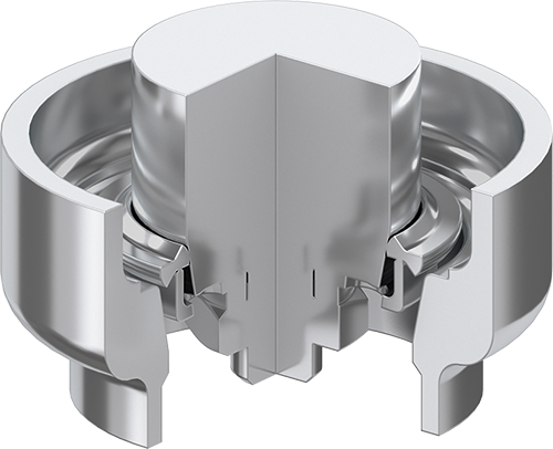
This dynamic, all-metal sealing system is characterized by consistent sealing and closing forces. It enables to reach high sealing forces with comparably low axial forces. The sealing partners are in stainless steel and deformed elastically only. The FLEX VATRING system is suitable for extreme UHV. It may be baked to 300 °C in open and closed position and if operated under clean conditions reaches a lifetime of > 1 000 cycles.
Fluoro (FKM or FPM) is an elastomer with high chemical resistance. Fluoro elastomers from different manufacturers have slightly different properties regarding chemical resistance, temperature resistance, mechanical properties and cleanliness.
Short term for flat panel display. Designates flat screen that are, for example, used in TV sets or computers.
The lubricant used in the vacuum is a fluoro-based vacuum grease. Solid lubricants and metal films are normally not mentioned as lubricants.
Free of lubricants or dry means that friction problems in the vacuum are solved in a way not to emit any hydrocarbon or silicone vapors into the vacuum.
Additional gas flow directly into the valve. A low overpressure reduces the gas penetration into the valve interior to a large extent, and valve mechanism and seal are protected against contamination.
Gas purge is only useful in combination with protective rings. The protective ring minimizes the additional gas penetration and the influence on the process. The kind of gas and volume of gas flow depend on the process. Usually, the gas purge is about 5% of the process gas flow.
Series 17 valves are available with a port for gas purging.
Unit for the energy dose in the SI system (international measuring system). The energy dose is the radiation energy absorbed by the material per unit of mass.
1 Gy = 1 J/kg = 100 rad
High purity is a collective term for cleanliness specifications which meet highest customer requirements regarding particles, organic and inorganic substances. High purity processes cover the entire manufacturing process from the production and cleaning of individual parts to the assembly and packaging of products.
Area with (locally) increased radiation level and increased temperature. The radiation level is higher than normally used materials can withstand during the expected time of use.
Valves are typically radiation resistant between 103 and 106 Gy depending on the sealing materials used. Actuators are typically suited for 101 to 105 Gy.
Only all-metal valves with a special actuator are suited for higher radiation levels.
Most pneumatically actuated VAT valves can optionally be equipped with an impulse solenoid. For actuation, the valve needs only a short electric pulse of > 50 ms. Between actuations the solenoid is currentless (but can also stay under voltage). This ensures no change of valve position at power failure.
To reduce the leak rate of static seals, rotary and shaft feedthroughs can be double sealed in order to evacuate the space between the two seals. This intermediate space is typically pumped to a pressure of 0.1 to 10 mbar. The lower differential pressure reduces the permeation through the seal and the gas carrying during actuation.
Helium gas flow in mbar Is-1 leaking through a sealing arrangement or a body. During the measurement, the difference of the helium partial pressure is in the order of 1 000 mbar. The rise of the helium gas flow during the test time (typically 1 minute) is the leak rate. The test time depends on the permeation rate of helium through the gasket and the vacuum time constant of the system.
Numbers of cycles (open-close-open) for which a valve can be safely operated under clean conditions and normal temperatures without any maintenance.
L-motion stands for a mechanically triggered real L-actuation of the gate in combination with a patented gate / shaft connection which enables a uniform seal compression.
A valve mechanism is mechanically locked if the sealing force remains intact at the failure of the closing force. This is normally accomplished by a joint going over center.
Especially designed for aggressive semiconductor applications. This L-movement transfer valve comes with vulcanized or O-ring gate seals and its L-motion is mechanically ensured. L-VAT features a very reliable single-shaft actuator, a bellows-sealed feedthrough and enables quick and simple maintenance.
Only metallic materials that comply with the applicable international quality standards are used. For steel, the requirements of EN 10088 or the corresponding ASTM regulations apply. In the case of aluminum, the standards EN 485 and EN 573 are observed. For all other metallic materials, appropriate regulations and standards are applied analogously.
Sealing configuration for elastomer sealed gate valves and transfer valves developed and patented by VAT. It features shock-free and virtually particle-free actuation and a very long lifetime.
Short form for nitrile-butadiene rubber (NBR). It is an elastomer material for gaskets.
Size denomination of a flange. The nominal I.D. (DN) does not always correspond to the smallest diameter of a flange or tube.
The opening direction is defined as the direction in which the gate is retracted from the seat during opening.
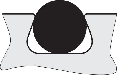
O-ring seals are made of materials with properties similar to rubber. They are put into grooves. Due to the compression, the O-ring is pressed into the groove. Small voids remain between the seal groove and the O-ring.
Also see "vulcanized seal".
The outgassing rate (in mbar Is-1) is the sum of all gas loads caused by:
A small outgassing rate is essential for efficient pump down and low base pressure. In valve manufacturing, a small outgassing rate is achieved by:
Particles in valves are mainly generated by friction of the valve components. VAT develops and uses a variety of inspection devices to detect particles. The inspections take place in VAT’s own laboratory. This makes it possible to get profound knowledge about the particle emission of our valves and to improve the quality of the valve components accordingly.
Depending on the field of application of the valves, particle emissions are either detected by means of optical measuring devices (particles > 300 nm) or by using a differential mobility analyzer (particles > 10 nm).
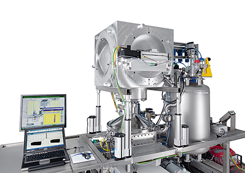
VAT particle test stand for particles > 10 nm
Short form for polyetheretherketone, a high temperature resistant thermoplast.
Perfluoro (FFKM or FFPM) is fully fluorinated hydrogenfree FKM. Its chemical resistance is even higher than that of FKM.
Permeation is a multi-stage process. Gas adsorbed at the outer wall is dissolved in the material, diffuses through the material and desorbs from the inner wall. For stainless steel, gas flows due to permeation can be neglected for the temperature used in vacuum technology. These gas flows have however to be taken into account for elastomer and plastomer gaskets.
For FKM the permeation rates "P" have approx. the following values after a long time at room temperature:
He P = 10 × 10-8 cm2 s-1
O2 P = 1 × 10⁻⁸ cm2 s-1
N2 P = 0.6 × 10⁻⁸ cm2 s-1
For a body with the area "A" (cm2) and the average diffusion length "I" (cm) the gas flow "Q" due to permeation at a pressure difference "Δp" (mbar) is around:
Q = P × A/I × Δp (mbar ls-1)
For air at atmospheric pressure the partial pressures "p" of the relevant gases are:
He p = 5.0 × 10⁻³ mbar
O2 p = 2.1 × 10² mbar
N2 p = 7.8 × 10² mbar
For well degassed O-rings the permeation of nitrogen and oxygen of the air through the FKM is the major contributor to outgassing.
The helium gas flow due to permeation may cause large leaks after a certain period of time during leak testing, depending on the gasket.
There are three types of Teflon®: PTFE, FEP and PFA. In this catalog, the word Teflon® is only used for Teflon PTFE.
High chemical resistance (similar to PTFE), but higher mechanical stability and hardness. PFA is used for chemically very resistant gaskets.
Name for materials which are used for predominantly plastically deformable gaskets (e.g. PFA, Tenic®).
VAT valves are available with various types of compressed air cylinders and various solenoid valves. Even for non-mechanically locked valves, the valve position can be maintained for a certain period of time at compressed air failure by installing a nonreturn valve at the compressed air inlet.
Short form for Polyoxymethylene, a thermoplastic material.
Vacuum pressures are always absolute pressures unless explicitly specified as pressure differences.
Compressed air pressures are always pressure differences to the atmospheric pressure, e.g., overpressures.
Elements:
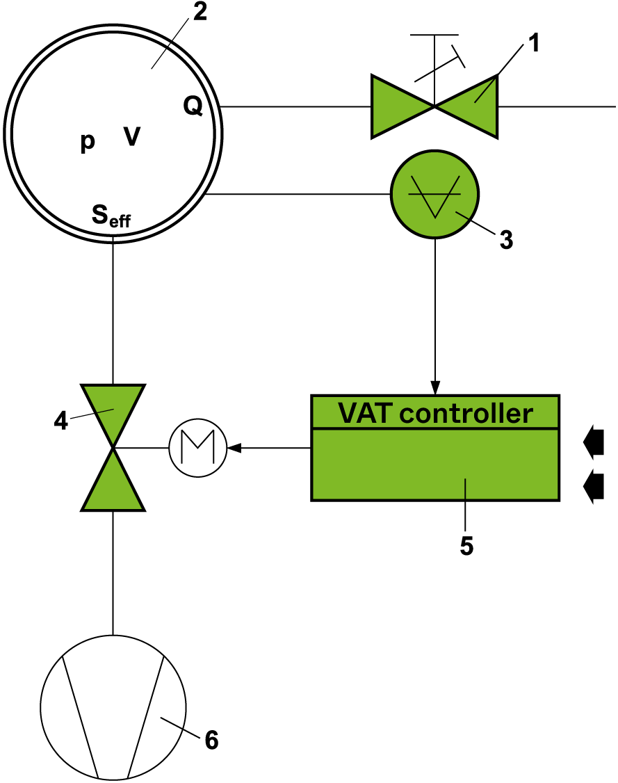
1. Gas flow meter
2. Process chamber
3. Pressure sensor
4. Control valve
5. Pressure controller
6. Vacuum pump
In stationary condition, the following formula is applicable:
Seff … Q/p
Seff … Effective pumping speed (ls-1)
Q … Gas flow (mbar ls-1)
p … Pressure (mbar)
or units used in the USA
Seff = 12.7 × Q/p
Seff … Effective pumping speed (ls-1)
Q … Gas flow (sccm)
p … Pressure (mTorr)
Principle of operation:
The controller compares the actual pressure in the process chamber given by the pressure sensor with the preset pressure. The controller uses the difference between actual and set pressure to calculate the correct position of the control valve. The controller drives the control valve into the correct position and the actual pressure again equals the set pressure.
This control operation is performed continuously. Pressure changes in the process chamber due to leaks, desorption, gas flow, reaction products, variations in pumping speed, etc. are always corrected at once.
In a vacuum system which is pumped and into which gas is admitted at the same time, the pressure can be controlled in two ways:
In an open gate valve the protective ring bridges the opening between the flanges. To the gas flow the open valve looks like a tube, i.e., has no changes in inner diameter.
The protective ring improves the gas flow, reduces the contamination of the valve interior and protects the gate seal from heat radiation (e.g., if the gate valve is used as a lock for hot items). An additional gas purge helps to protect the valve interior completely.
Short term for photovoltaics. Designates the technology for transforming sunlight into electrical energy.
The high quality level of VAT valves is planned according to the TQM (total quality management) system and constantly monitored during manufacturing and assembly. Monitoring is performed with SPC (statistical process control) in combination with modern measuring machines, such as 3D coordinate measuring instruments and automated valve testing machines with automatic data recording.
The following tests are performed on each VAT valve:
Parts / subassemblies:
Complete valve:
Additional tests can be performed and certificates of conformity, acceptance test certificates, inspection certificates and material certificates can be supplied on customer request.
Use of special materials increases the service life under ionizing radiation over that of normal valves. The radiation resistance in Gray is the dose up to which the valve functions safely (1 Gray = 100 rad).
This guarantees a small RF resistance through the open valve. In the open valve position a metal ring, having the geometric shape of the beam tube, is spread between the two connecting flanges and ensures a direct electrically conducting connection between the two flanges.
A rotary feedthrough is an element to transmit a rotation or pivoting motion into the valve interior. VAT's rotary feedthroughs are elastomer sealed and lubricated with a fluoro based vacuum grease. The gas carry-over into the valve interior is much smaller than for a shaft feedthrough of the same diameter.
The operating costs are substantially lower than for a bellows feedthrough due to the long cycle life and the low costs for spare parts (no bellows).
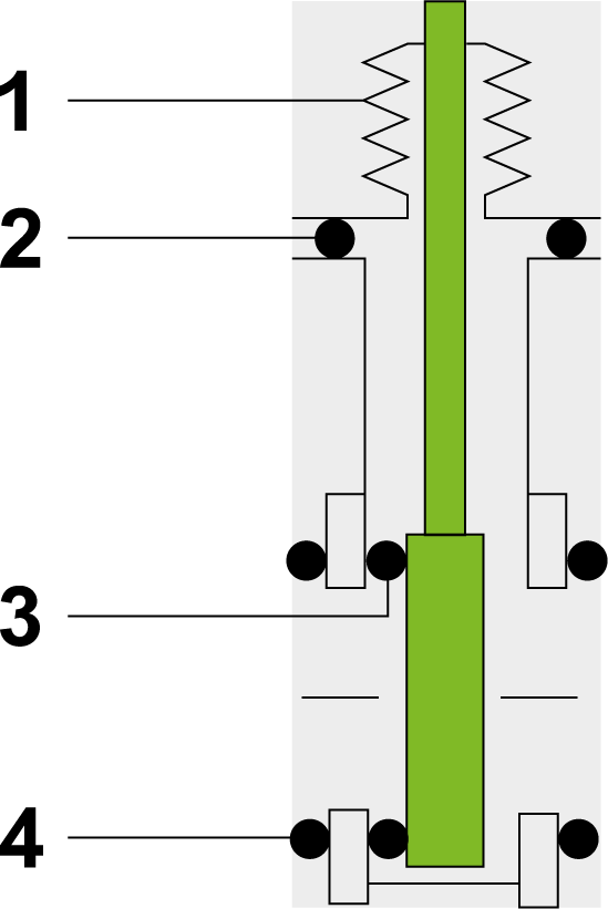
1. Actuator feedthrough
2. Bonnet seal
3. Gate seal
4. Flange seal
Some valves also have a seal between the bonnet flange and the actuator assembly. This seal is made of the same material as the bonnet seal.
Short form for symmetrical flow valve. Valve concept at which the process gas flow is symmetrical around the gate during pressure control.
A shaft feedthrough consists of an O-ring and a stem and transmits a linear motion into the valve interior. The elastomer gasket is lubricated with a fluoro-based high-vacuum grease.
During closing a short-term pressure rise may occur in the valve body.
A shutter reduces the full conductance in a very short time to a small leak (not vacuum tight). This prevents the shock wave of an air inrush from spreading. Shutters are compatible with all-metal systems.
In connection with gaskets a short form for silicone rubber.
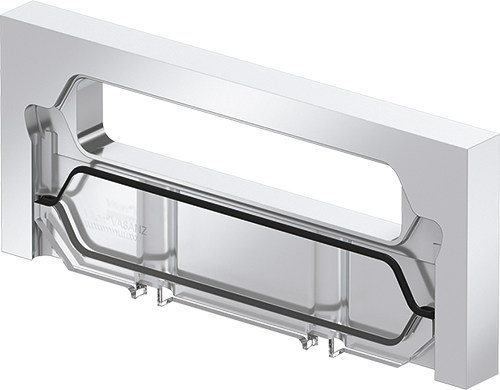
A valve primarily developed for the solar module production featuring a special, VAT-invented locking system. Leaktight closing is performed by a plate provided with an O-ring seal. The SolVAT valve is based on a modular design. Scaling for the required substrate size is hence easy. The valve is very robust against aggressive media and high temperatures and may be supplied in a variety of materials and material combinations.
The stepper motor is well suited for exact positioning. It is hence often used as actuator for control valves.
Teflon® (PTFE) filled with nickel powder. Sealing material for the chemical industry.
Joining technique for void-free joints.
In addition vacuum brazing is an ideal way of cleaning and degassing the brazed parts.
For valves with lubricants VAT uses a fluoro-based vacuum grease with very low vapour pressure (< 5 × 10-13 mbar at 20 °C).
Valve network consisting of a master and one or more slave valves. The master valve is controlled by the host system while the slave valves will follow the master.
Side of the gate seal indicated with the sign  a in the dimensional drawings. Each VAT valve has a triangle
  stamped into the flange on the seat side. The tip of the triangle points towards the seat. This information is important in connection with differential pressure (see differential pressure).
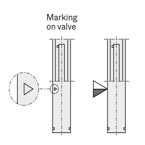
Gate valve mechanism (e.g., used in series 10, 11, 12, 14) developed by VAT.
Gate valves with VATLOCK system are mechanically locked in the closed position.
In the open position the mechanism is not locked. Leaf springs hold gate and counter-plate against the carriage with the ball retainers. The ball pairs are in the detents.
For closing, the mechanism is moved forward into the closing position.
The locking starts after the leaf spring stop touches the body. The ball retainers move the ball pairs out of the detents. Gate and counter plate are spread apart. The gate seal is pressed against the sealing surface without scuffing. The arrangement of ball pairs ensures an increase of the sealing force with vacuum on either side of the gate.
During opening, the movements proceed in the reverse order.
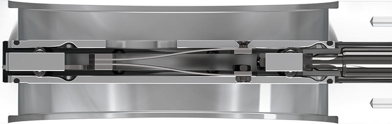
This dynamic, all-metal sealing system is characterized by consistent sealing and closing forces. It enables to reach high sealing forces with comparably low closing resp. axial forces. The sealing partners are in stainless steel and deformed elastically only. The VATRING system is suitable for extreme UHV. It may be baked to 450 °C in open and 350 °C in closed position and reaches a lifetime of > 100 000 cycles if operated under clean conditions.
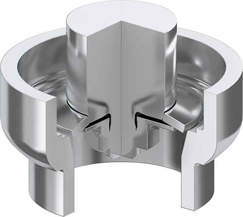
This metal flange seal developed and patented by VAT requires only parallel flanges with carefully prepared flat sealing surfaces.
VATTERFLY valves can-at first look-be easily mistaken for butterfly valves. They are pivoting plate valves that in many cases are a compact economical alternative to a gate valve. In VATTERFLY valves the gate first swings to the closing position without any friction of the gate seal. For vacuum tight closing and locking, the plate pivots. The sealing procedure is similar to that of a gate valve.
VATTERFLY valves of the Series 20.3/20.4 feature a rotary feedthrough.
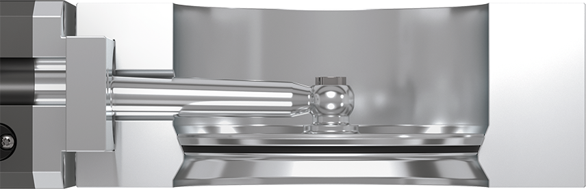
Is used as a dynamic seal for UHV valves and MONOVAT systems (e.g., series 01, 02, 03, 04, 05, 10.8, 15, 20).
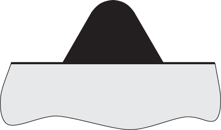
The vulcanized seal has the following advantages compared to an O-ring seal:
Vulcanized seals can be made of fluoro elastomer, perfluoro-elastomers, silicones or EPDM. Outgassing rate, permeation and bakeability are equal to selected high quality O-rings.
In the open position, a tube is placed between the flanges. Only a small gap remains between the ends of the tube and the flanges. The RF resistance of the open valve is hence greatly reduced.
Sealing system developed by VAT for the Series 09 Gate Valves.
This extremely robust system is provided with a wedge-shaped gate which is pressed on an appropriate seat in the body. O-ring compression is limited by PEEK sliding elements. This enables a combination of a good leak rate with a corresponding cycle life, even if exposed to multiple differential pressure openings of up to 1 bar. Furthermore, the sliding elements prevent dynamic metal-to-metal contact and consequently reduce particle generation. This may be crucial for sensitive applications.
A valve can be equipped with a weld neck instead of a flange. Such a valve can be welded directly into a tubing or a specific flange can be attached by the customer. Care has to be taken not to warp or contaminate the valve.
L-movement transfer valve with an O-ring gate seal, primarily developed for the flat screen production. The XL-VAT valve is based on a modular design. Scaling for the required substrate size is hence easy. The required locking pressure may be controlled via the control unit. Overstraining of the gate O-ring may therefore be prevented. Furthermore, the XL-VAT valve is designed for very easy maintenance.